LCDs (Liquid Crystal Displays) are a widely used technology for displaying text and simple graphics on electronic devices. The 2-line, 16-character displays with the Hitachi HD44780 chipset are particularly popular in the field of microcontroller projects, e.g. with Arduino or ESP. These displays are inexpensive, easy to use and offer good visibility.
Main features:
- Lines and characters: 2 lines with 16 characters each.
- Chipset: Hitachi HD44780, the de facto standard for such displays.
- Control: Simple control via 4-bit or 8-bit data bus.
- Power supply: Operating voltage typically 5V.
- Illumination: Usually with backlighting for better visibility even in poor lighting conditions.
- I2C Bus: It is also possible to operate the display with the HW-061 module via the I2C bus.
These displays are ideal for DIY projects and applications where a simple but effective text display is required.
Setting up the circuit with the ESP32
Parts required:


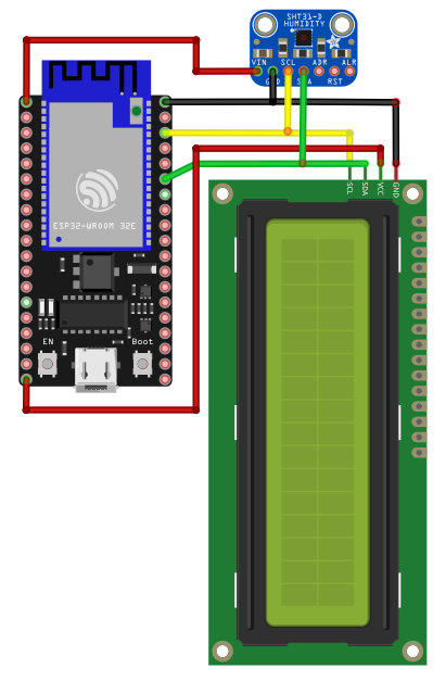
Here we use the existing structure of the measuring circuit with the SHT3x and add a display to show the temperature and humidity.
This is an I2C bus-capable display, which makes the setup relatively simple.
In principle, we only need to connect the 4 wires in parallel to the sensor connections. In principle, this means that the supply voltage of the display is 5 volts.
I have therefore connected VCC to PIN 19 5V.
We had set 0x44 for the I2C bus on the STH3x sensor. The display runs at address 0x27, so there are no collisions and each module can be addressed correctly. Should this nevertheless occur in your own setup, the Hamm/Lippstadt University of Applied Sciences website can help. Addressing is described very well here.
Programming with VS Studio Code
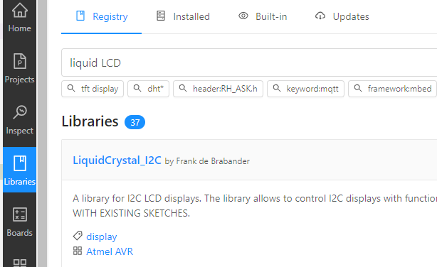
We need a library for the display, which we quickly found.
And that was all the requirements.

The platform.ini now looks like this.
[env:esp32dev]
platform = espressif32
board = esp32dev
framework = arduino
lib_deps =
adafruit/Adafruit SHT31 Library@^2.2.2
marcoschwartz/LiquidCrystal_I2C@^1.1.4
monitor_speed = 9600
Let’s take a look at the code.
//Program Eckhard Gerwien - partial verification by ChatGPT

#include <Arduino.h>
#include <Wire.h>
#include <SPI.h>
#include <LiquidCrystal_I2C.h>
#include <Adafruit_SHT31.h>
#define I2C_SDA 21
#define I2C_SCL 22

// Create an object for the SHT31 sensor
Adafruit_SHT31 sht31 = Adafruit_SHT31();
// set the LCD address to 0x27 for a 16 chars and 2 line display
LiquidCrystal_I2C lcd(0x27,20,4);

void printlcd(byte, byte, String);

void setup() {
    // Initialisierung des I2C-Bus
  Wire.begin(I2C_SDA, I2C_SCL);

  // Initialization of serial communication for debugging
  Serial.begin(9600);

  //Initialize LCD display and delete display
  lcd.init();
  lcd.backlight();
  lcd.clear();

  //in the first line of the display
  printlcd(0,0,"DIYTechAdventure");

  // Initialization of the SHT31 sensor
    if (!sht31.begin(0x44)) {
    Serial.println("SHT31 not found!");
    while (1);
  }
  Serial.println("SHT31 Sensor found!");
}

void loop()
{
  // Reading the temperature
  float temperature = sht31.readTemperature();

  // Reading the humidity
  float humidity = sht31.readHumidity();
  // Check if the measured values are valid
  if (!isnan(temperature)) {  // isnan checks whether the value is 'NaN' (Not a Number)
    Serial.print("Temperature: ");
    Serial.print(temperature);
    Serial.println(" °C");
// Buffer for displaying the temperature
  char tempStr[6];
  // Convert temperature to string, 4 total digits, 1 decimal place
  dtostrf(temperature, 4, 1, tempStr);
  printlcd(0,1,"T:" + String(tempStr));
  } else {
    Serial.println("Error when reading the temperature");
    printlcd(0,1,"T:ER");
  }

  if (!isnan(humidity)) {
    Serial.print("Humidity: ");
    Serial.print(humidity);
    Serial.println(" %");
    //Set cursor and write text at the corresponding position in the display
    printlcd(8,1,"H:" + String(humidity));
  } else {
    Serial.println("Error when reading the humidity");
    printlcd(8,1,"H:ERR");
  }

  // Waiting time of 10 seconds before the next measurement
  delay(10000);
}

void printlcd(byte posx, byte posy, String Text)
{
  lcd.setCursor(posx, posy);
  lcd.print(Text);
}
In the #Include part, the above-mentioned library for controlling the display is added.
Then I define the PINs for connecting the data lines of the I2C bus.
The address assignment for the sensor and the display is already explained in the code.
void printlcd(byte, byte, String); – is the function declaration, which can then also be placed after the loop.
I like to use this form because the code seems tidier.
In Setup(), I then use the declared function for the first time to write the first line of the display:
printlcd(0,0, “DIYTechAdventure”); The display first addresses the columns, then the rows. so 0,0 means first column, first row – 8,1 is then the 9th column, 2nd row. In the void printlcd(byte posx, byte posy, String Text) function, the column and row are set with lcd.setCursor and then the text is written to this position with lcd.print().
// Buffer for displaying the temperature
char tempStr[6];
// Convert temperature to string, 4 total digits, 1 decimal place
dtostrf(temperature, 4, 1, tempStr);
printlcd(0,1,”T:” + String(tempStr));
Challenge: At this point, I want to output the temperature with only one decimal place. So I put the temperature read into the buffer and convert float to string and at the same time specify that I only need 4 characters and one of them after the decimal point.
I also put this back into the function call for writing the display.
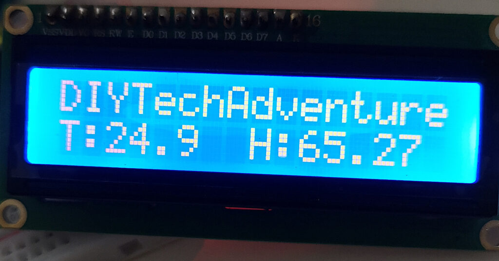
If everything went correctly, you should get this. First line the permanently programmed output. Second line temperature and humidity, which is updated every 10 seconds.

It should also be mentioned that we are using 2 different operating voltages here. As usual with the ESP32, it runs with 3.3V. The display, however, runs on 5V. The sensor has a larger supply range (between 2.1 and 5.5V). Please note the voltage tolerance of the ESP PINs.
We’ve reached the end of another DIYTechAdventure. Have fun rebuilding and if you have any questions, please use the comment function.
