The DS18B20 is a digital temperature sensor that is used to accurately measure temperatures in a wide range from -55°C to +125°C. It communicates via a 1-wire protocol, which means that it can be operated with just one data line (plus ground and supply voltage). This makes it easy to connect multiple sensors to a single bus.
Important features of the DS18B20:
Setup of a measuring circuit with a sensor and the ESP8266
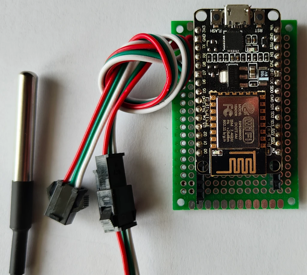
Parts required:
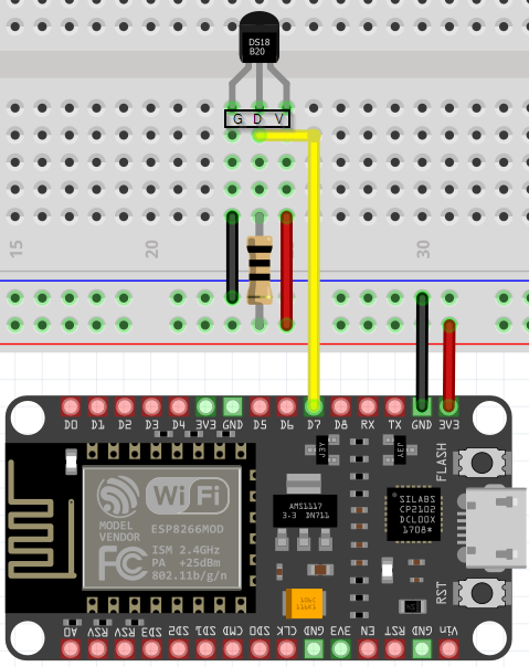
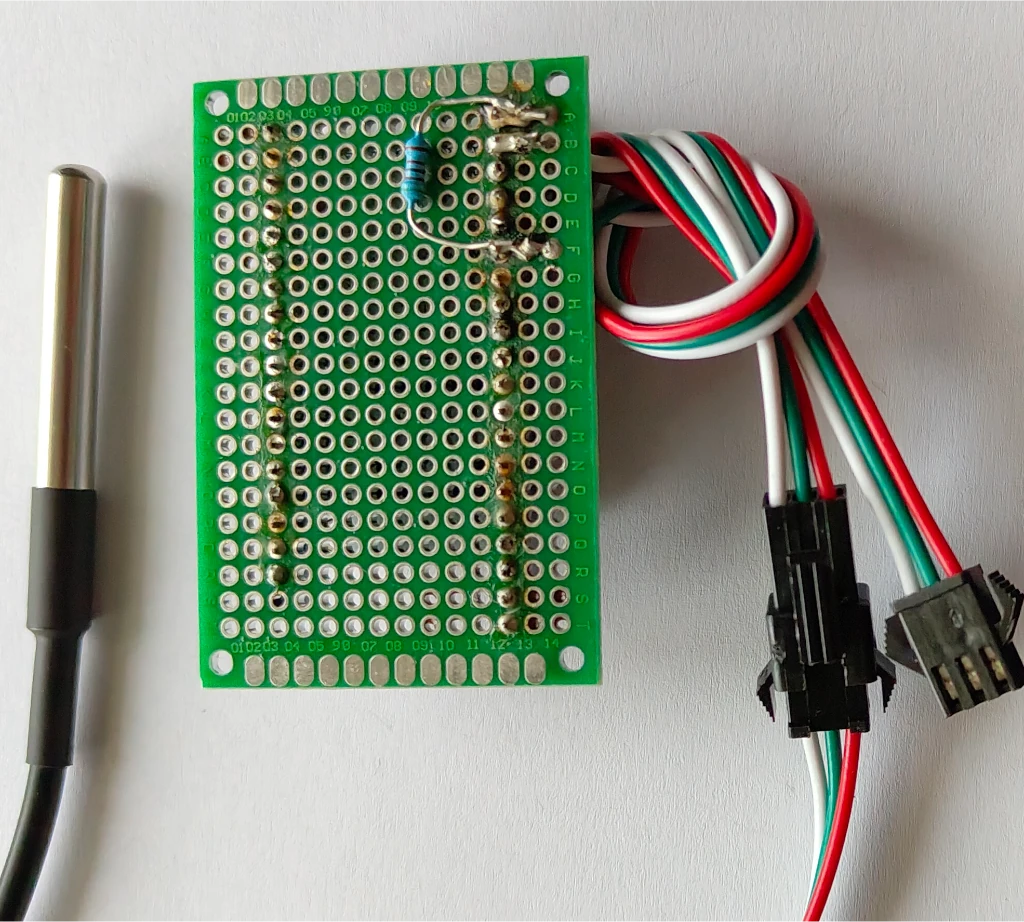
The construction of the circuit is quite simple:
I like to use breadboards with header pins to build experimental circuits. This structure can then be used again and again, e.g. to include further components. The circuit of the DS18B20 is also shown (G=Ground; D=data line; V=supply voltage)

Programming with the Arduino IDE
Prerequisite -> Installed Arduino IDE
Install the required libraries.
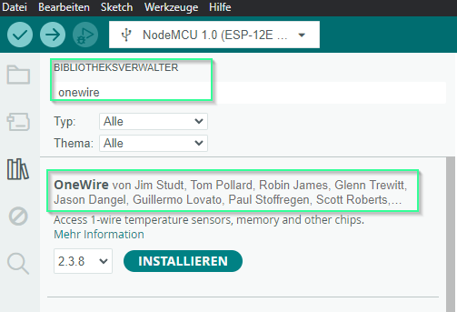
The code requires the 2 libraries OneWire.h and DallasTemperature.h. These must be installed if not already done. The following screenshots show you how to install them.
Please go to the library manager and search for “OneWire”. The OneWire will be listed as I have marked it. You will see the current version and the “Install” button. Click on this too.
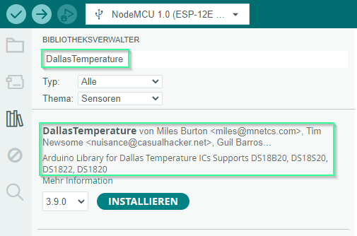
Proceed in the same way with the 2nd library. Search for DallasTemperature and find this library.
Please install this as well. Then restart the Arduino IDE once.
The code for reading the temperature
// Integrating the required libraries
#include <OneWire.h>
#include <DallasTemperature.h>

// The data line is connected to D7 on the ESP8266
define ONE_WIRE_BUS 13

// Setting up a oneWire instance for communication with the OneWire devices
OneWire oneWire(ONE_WIRE_BUS);

// Transfer of our oneWire reference to the Dallas temperature sensor
DallasTemperature sensors(&oneWire);

void setup()
{
// Start serial communication
Serial.begin(115200);
// Calling the method
sensors.begin();
}

void loop()
{
// Aufruf sensors.requestTemperatures(), to trigger a global temperature measurement
// All sensors on the bus are queried
Serial.print("Requesting temperatures…");
sensors.requestTemperatures(); // Triggering temperature measurement
Serial.println("DONE");
Serial.print("Temperature for the device 1 (index 0) is: ");
Serial.println(sensors.getTempCByIndex(0)); // Warum "byIndex"?
// We can operate more than one sensor on the bus.
// 0 refers to the first IC

delay(10000);// Wait 10 seconds
}
Upload the tested code

The code is checked syntactically with the left button. To compile the code and upload it to the board, use the arrow to the right.
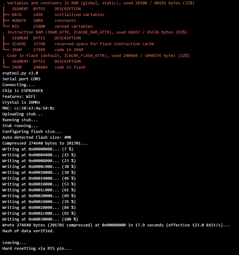
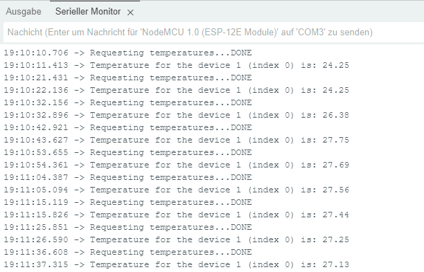
And here we have the output of our sketch.
A measurement is triggered and output every 10 seconds
Adding a sensor to the circuit
It is very easy to integrate another sensor into the circuit. I’ll show you the schematic on the breadboard.
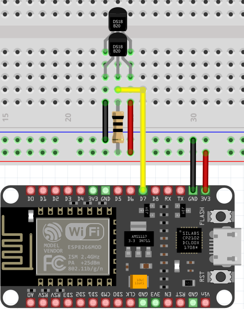

Here I present the loop loop from the above code with the extension for reading another sensor.
void loop()
{
  // call sensors.requestTemperatures() to trigger a global temperature measurement
  // all sensors on the bus are queried
  Serial.print("Requesting temperatures...");
  sensors.requestTemperatures(); // Trigger temperature measurement
  Serial.println("DONE");
  Serial.print("Temperature for the device 1 (index 0) is: ");
  Serial.println(sensors.getTempCByIndex(0)); // Warum "byIndex"?
  // We can operate more than one sensor on the bus.
  // 0 refers to the first sensor
  Serial.print("Temperature for the device 2 (index 1) is: ");
  Serial.println(sensors.getTempCByIndex(1));
  // Index 1 refers to the second sensor
  delay(10000);
}
And with further small changes, it is also possible that we do not have to worry about the number of connected sensors. A For loop can do this for us.
void loop()
{
  // call sensors.requestTemperatures() to trigger a global temperature measurement
  // all sensors on the bus are queried
  Serial.print("Requesting temperatures...");
  sensors.requestTemperatures(); // Trigger temperature measurement
  Serial.println("DONE");

  // Query the sensors in a loop
  for (int i = 0; i < sensors.getDeviceCount(); i++) {
    Serial.print("Temperature for device ");
    Serial.print(i);
    Serial.print(" is: ");
    Serial.println(sensors.getTempCByIndex(i));
  }

  delay(10000); // Wait 10 seconds
}
Briefly about the structure of the for loop.
for (int i = 0; i < sensors.getDeviceCount(); i++) {
…………….
}
i is the counter and also represents the index number of the sensor.
With sensors.getDeviceCount() we ask for the number of connected sensors.
And with i++, i is increased by one with each loop pass so that we can read out the next sensor.
With the “<” operator, we ensure that the loop is terminated as soon as all available sensors have been read out.
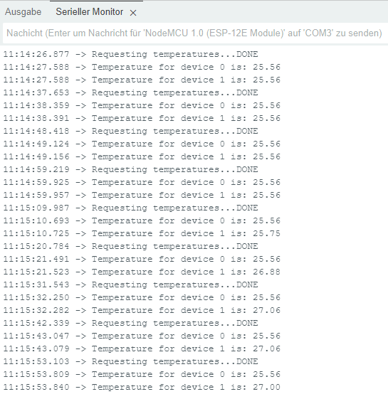
The result is the output of the measured values from both sensors. The accuracy of the sensors can be seen very clearly. Both measured values are the same until I briefly touched one sensor.
Here we are at the end of our DIYTechAdventure. I hope you were able to follow everything and come to similar conclusions.
If you have any questions, please use the opportunity to comment.
